Gated Comparator for music synthesizers. The idea for this project came when I was listening to some music in which part of the background was jumping between octaves in a semi-random fashion. Feeding noise into a comparator was my immediate thought, but I soon realized this wasn't going achieve what I wanted. I needed to be able to control when these jumps could occur. By feeding the output of the comparator into the Data input of a D type flip-flop, it is possible to control when the transition occurs by applying the rising edge of a pulse to the Clock input of the flip-flop. The result is a random level (on or off) at a predetermined time. As the flip-flop chosen (the 4013) was a dual flip-flop, as second stage was also easy to add, effectively forming a two-stage shift register. Each also has complimentary outputs, adding to the versatility. The prototype also has two transistor based LED drivers, indicating when a stage is on, though these have been omitted from the circuit diagram. On the prototype system, LEDs are powered from a separate supply to reduce supply rail fluctuations, an unnecessary complication for this article.
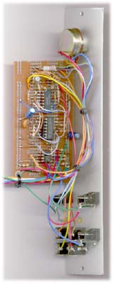
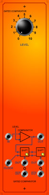
 The circuit consists of two comparators, one adjustable by a front panel knob, for processing the input signal, and the other to square up the gate signal and provide some isolation for the CMOS flip-flops (4013B). The output of the signal comparator is fed to an output jack via a 1k resistor. Of note is that this output swings between positive and negative, as distinct from positive and 0v like all other outputs in this module. The outputs of these comparitors are converted to levels suitable for driving the 4013 by diode resistor combinations. The two flip-flops in the 4013 are clocked from the same source. The signal being processed is fed into the D input of the first flip flop. The output of this flip flop is fed into the D input of the second flip-flop via a short R-C delay. Wired like this, the two flip-flops function like a two-stage shift register. The R-C delay is there to reduce false triggering of the second stage. All outputs of the flip-flops are buffered using conventional op-amp voltage followers made from LM358's before being fed to the output sockets via 1k resistors. The prototype used a single LM324 instead of two LM358's. The two 10mfd capacitors give some power supply isolation. Power rails could probably be almost anything from +/- 9V to +/- 15V, though I've only tested the unit on +/- 14V. Asymmetrical rail voltages should work, but the range of the pot will be affected, as will the direct comparator output. In this case the circuit was lashed up on a piece of "Designer Board" a PCB equivalent of one of those white "proto boards". 200 DPI B&W printable panel artwork. Article, art & design copyright 1999 by Ken Stone
|