|
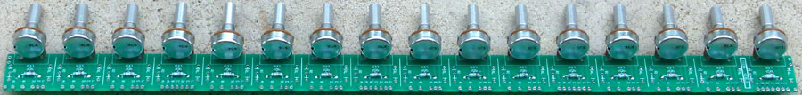
This PCB is designed to help mounting and wiring pots or LEDs to panels. It uses the 1 inch horizontal spacing standard of Serge panels, and provides mounting for 16 pots or LEDs. Vertical height is limited by the size of the pots you use. 16mm pots are too large for 1" vertical spacing, so you will need to use 9mm pots in that case. Pads for both footprints are included.
Pad identification:
Component identification. One of each part is required per cell used, dependent upon the application.
If you are using the board for pots, you probably won't want the LED related parts, and vice versa.
ConstructionBefore you start assembly, check the board for etching faults. Look for any shorts between tracks, or open circuits due to over etching. Take this opportunity to sand the edges of the board if needed, removing any splinters or rough edges.
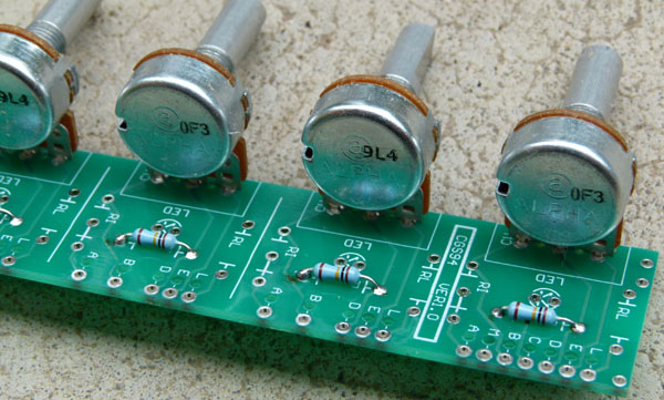
The CGS94 consists of 16 individual 'cells' at 1 inch spacing. Common to all cells are:
On the VER1.0 PCB there is an error with the pot pads. The inner CW pad is not connected to the outer CW pad. If you are using pots that use the outer pads, this is not a problem. If you use pots that have 0.1" spaced leads, you will need to join the two outer pads together. If the pot lead is long enough, just bend it across and solder it across both pads. If not, try bridging the pads with solder. 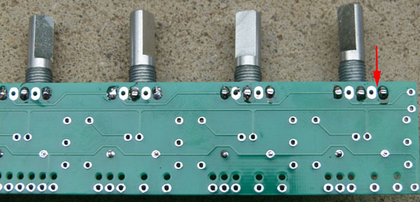
Parts listPart values will be determined by the circuit with which you are using this board.
ShippingDue to the cost of packing materials and the different shipping rates these boards will attract, shipping per order will be US$20. In other words, it will cost US$20 to ship one board or 20 board at the same time. I suggest you buy all you will need in a single transaction to reduce your costs. Other PCBs can of course be included for no extra shipping costs. Notes:
Parts list This is a guide only. Parts needed will vary with individual constructor's needs. Parts within the boxed area can be omitted if the switched outputs are not required. Check the PCBs for Sale page to see if I have any in stock.
Can't find the parts? See the parts FAQ to see if I've already answered the question. Also see the CGS Synth discussion group.
Article, art & design copyright 2013, 2014 by Ken Stone
|