|
This module is a variation on the 1973 Classic Serge Triple Bi-directional Router, and the 1975 Bi-directional Quad Switch modules. The TRIPLE BI-DIRECTIONAL ROUTER is a group of three switches each of which can route one input to either of two outputs, or either of two inputs to one output according to a pulse or control voltage level. Alternately, it can be assembled to sequentially route one input to one of four outputs, or one of four inputs to one output. The switches are true bidirectional switches. You can feed signals through them in either direction. Note that due to the limits of CMOS, it can switch signals that are up to about +/-7 volts. A little on how it works:
Triple Bi-directional Router.
Bi-directional Quad Switch.
Construction

Before you start assembly, check the board for etching faults. Look for any shorts between tracks, or open circuits due to over etching. Take this opportunity to sand the edges of the board if needed, removing any splinters or rough edges. When you are happy with the printed circuit board, construction can proceed as normal, starting with the resistors and diodes first, followed by the taller components. Take particular care with the orientation of the polarized components, such as electrolytics, diodes, ICs and transistors. If you are planning to use it with 6.3mm or 3.5mm jacks, the common of these jacks should be wired to 0V/GND as usual. Just solder the return wire to the (unused) center pins of the power connector. As presented, the circuit is set up for use with +/-12 volts. Connecting it to +/-15 volts requires the value of four resistors to be altered. In the regulator portion of the circuit (near the power connector) replace the two 2k2 resistors with 4k7. Replace the two 8k2 resistors with 10k. Failure to make this modification when running on +/-15 volts will cause the destruction of the CMOS chips. I would suggest powering the module for the first time without any chips in it and checking the voltage between the emitters of the two regulating transistors (2N3638 and 2N3566). If this voltage is over 15 volts, you will need to change the values of the resistors in the voltage divider. Transistor types are not critical. The PCB specifies the types found on the original version. BC557 can be used for the PNP and BC547 for the NPN. 2N3906 and 2N3904 can be used if installed backwards with respect to the outline on the overlay. Notes for the Triple Bi-directional Router. If you are building the Triple Bi-directional Router version, simply do not install the components in the outlined area on the PCB.
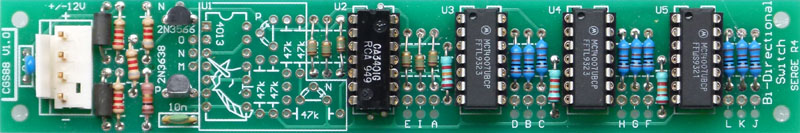
If you are Bi-directional Quad Switch, install all parts except for the 22k resistors. Wires need to be run from the pads marked M, N and O to one pad of each of the empty 22k resistor locations. See the photo above. You also need to link pads C to L and B to H complete the routing. In this configuration, the I input is the only one used. A positive gate or trigger signal will advance the switch to the next input/output.
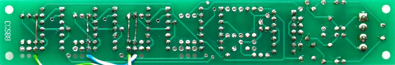
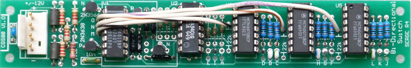
As the gates are in series, some the protection resistors are not required, but were present on the original Serge version, effectively doubling the resistance of the switch. You can replace these extra resistors with links. On the prototype, I shorted out the extra resistors on the rear of the PCB as shown above. 
Set UpThere is no setup.
For those interested, original Serge kit assembly and set-up instructions can be found here:
Info on the original Serge modules can be found here:
Notes:
Parts list
ROU - Part required only for Triple Bi-directional Router version. QBS - Part required only for Quad Bi-directional Switch version. This is a guide only. Parts needed will vary with individual constructor's needs. If anyone is interested in buying these boards, please check the PCBs for Sale page to see if I have any in stock. Can't find the parts? See the parts FAQ to see if I've already answered the question. Also see the CGS Synth discussion group.
Article, art & design copyright 2011 by Ken Stone
| ||||||||||||||||||||||||||||||||||||||||||||||||||||||||||||||||