|
Tube VCA / Timbral Gate for music synthesizers.
This is a tube based Voltage Controlled Amplifier / timbral gate. While this module basically operates as a VCA, it does add a degree of distortion to the signal. How much distortion depends on how hard it is driven. Add feedback and it begins to oscillate, synchronizing to the incoming signal to some extent. All this while running on a standard synthesizer power supply, with no extra heater supply required.
A demonstration of feedback oscillation and synchronizing on the Panther Euro version of this module.
A little on how it works.
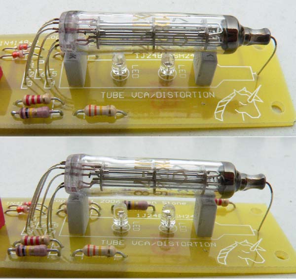
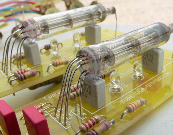
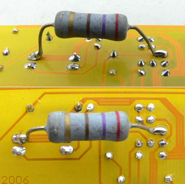
There are several distinct sections to this circuit. First to consider is the heater supply. The tube chosen is the Russian sub-miniature 1J24B (1SH24B, 1Ж24Б). It operates on low voltage, and uses a mere 13ma at 1.2 volts for its heater. In other words, the heater uses less power than the average LED. Power for the heater is derived from the negative rail, by passing the current through first the heater, then some current limiting resistors with LEDs in series with them. Two resistors have been used to keep the dissipation within the resistors to appropriate levels. The LEDs are also using a little of the waste power. More info on this is given alongside a photo below. The two 1N4148 are merely an insurance policy. They are to prevent the heater seeing any more than around 1.5 volts if an incorrect resistor is installed, or a similar mishap occurs. The top left of the schematic is a very standard summing amplifier/mixer with unity gain. It's output is AC coupled to the grid of the tube. The bottom left of the schematic is a very standard summing amplifier/mixer with a gain of around 2. It's output is fed through a "de-thump" lag circuit and into a second stage, also with a gain of around 2. This part of the circuit is the CV mixer. It converts the expected 0 to 5 volt CV signal into something appropriate for driving the second grid of the tube by both amplifying it and adding an offset voltage. The core of the circuit is of course the tube itself. It can be viewed as running on a 30 volt single rail supply, as its cathode is referenced to the negative 15 volt rail instead of 0 volts. It is a mixture of a triode wired pentode and a multiplier, though sans the usual automatic cathode bias, due to the use of a directly heated cathode. The final section of the circuit is simply a load-independent, non-inverting buffer/gain stage.
Construction
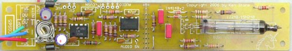
Before you start assembly, check the board for etching faults. Look for any shorts between tracks, or open circuits due to over etching. Take this opportunity to sand the edges of the board if needed, removing any splinters or rough edges. (With the boards supplied by me, the edges are already milled, and etching faults are very rare.) When you are happy with the printed circuit board, construction can proceed as normal, starting with the resistors first, followed by the IC socket if used, then moving onto the taller components. Take particular care with the orientation of the polarized components such as electrolytics, diodes, transistors and ICs. When inserting ICs into sockets, take care not to accidentally bend any of the pins under the chip. Also, make sure the notch on the chip is aligned with the notch marked on the PCB overlay.
Do not replace the LM358 with another type. It was chosen for its ability to drive down to its negative rail. Setting up involves adjusting one trimmer. Set the panel CV controls to their zero position, and feed a signal into the input. Make sure you have the input level/drive pot turned at least part way up. Adjust the trimmer until a signal is heard at the output, then back off until it just stops. CV Init is used to set the VCA to zero gain at 0 volts CV input. Feed an audio signal into an input, and monitor the output. With no CV at any of the inputs, and the optional external Initial Gain pot, if used, set to its zero position, adjust this until no signal is heard.
Modifications Read Tube vca modifications and results on electro-music.com forum for more ideas. On the first (yellow) run of PCBs, the grid bias resistor (330k) goes to the negative rail. In this position, it causes some distortion of the signal. This can be a good thing. I prefer the resistor in this position when using the unit as a timbral gate. This is shown in BLUE on the schematic. An alternative is to bias the grid to around 1.2V with respect to the negative rail - in other words, to the other end of the heater/cathode. This is shown in RED on the schematic. Doing so will reduce the distortion at low input levels. Do not put in both red and blue options at the same time or you will short out the heater. It may be appropriate to connect pin 4 of the tube to pin 1 of the tube instead of pin 2 as well, if making this modification. It is possible to increase the value of the plate resistor. I would not go above 27k, as strange (not good) things start happening. Increasing the value of this resistor will increase the over all gain, and may reduce the distortion at low signal levels. If you get too much gain doing this, overall gain can be reduced by increasing or even removing the 100k resistor marked "Gain" in RED on the schematic. Removing it convert the output gain stage to a 1:1 buffer. Reducing the value of the 100k between pin5 and 0 volts may also help reduce gain. Alternately if you wish to increase the gain of the output buffer, reduce the value of the 100k resistor marked "Gain" in RED on the schematic. 10k would give a gain of 10. Positive feedback adds some versatility to this unit. It isn't really a modification. Just make sure you have two audio inputs with level pots, one for the incoming signal, and the other for direct connection to the output. Having two output jacks would of course make wiring this up easy. Alternatively you could normalize the output to one of the input jacks. Rev 1.1 PCB Install the 330k in the position marked "330k" AND the jumper in the position marked with a dashed line*, OR Install the 330k in the position with no value specified AND the jumper in the position marked with a solid line*. * note that the above two connections were incorrectly displayed on this page until updated on 15 Nov 2008. No real harm will come if the incorrect wiring was followed. Pins 1 and 2 of the tube can be swapped by installing them in the two holes next to the ones marked 1 and 2 (saves getting the wires crossed). Notes:
Parts list This is a guide only. Parts needed will vary with individual constructor's needs. If anyone is interested in buying these boards, please check the PCBs for Sale page to see if I have any in stock.
Can't find the parts? See the parts FAQ to see if I've already answered the question. Also see the CGS Synth discussion group.
Article, art & design copyright 2006 by Ken Stone
| |||||||||||||||||||||||||||||||||||||||||||||||||||||||