This is a smaller version of the Stomp Box Adapter and is basically for use in the reverse situation - namely to allow use of stomp-boxes (effects pedals, effects racks etc.) as part of a synthesizer setup. While the original will do the job, this one dispenses with the power supply and bypass switching, and handles a single channel.
A little on how it works:
The schematic of the Stomp Box Adapter. The connections to the right go to the panel mounted jacks of the type used by the rest of your synthesizer, while the jacks to the left are 6.5mm for connection to the stomp-box. Modular synthesizers generally use much higher signal levels than are used in effects pedals, so directly connection the two will create two problems. First, the excessive signal will cause the input of the effects pedal to overload/distort. Second, the output from effects pedal is too weak to drive synthesizer modules without some amplification. To compensate for these problems, the signal from the synthesizer must be dropped to a fraction of what it was, while the output of the effects pedal must be amplified by the same amount to restore it to a level suitable for the synthesizer. I have chosen to use a ratio of 20 as this encompases the signal levels of many synths. If you know for certain that the ratio is too great, the ratio can be reduced to reduce the amplification of any effects pedal noise. For example, if an effects pedal works on a 1V p-p signal, and a synthesizer has a maximum output of 5V p-p, a ratio of 5 would be adequate. The preamplifier of the stomp box adapter is a basic non-inverting amplifier with an AC gain of 20, and suppression capacitors as needed. Their input impedance is approximately 150k. The AC gain can be reduced if need by by increasing the value of the 470R resistor. For example, a 1k resistor in this position would give a gain of 10. The 1k resistor of the input divider would need to be increased to 2k2 to keep the drop and gain matched.
Construction
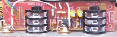
The component overlay. Connections can be determined from the circuit diagram. Before you start assembly, check the board for etching faults. Look for any shorts between tracks, or open circuits due to over etching. Take this opportunity to sand the edges of the board if needed, removing any splinters or rough edges. When you are happy with the printed circuit board, construction can proceed as normal, starting with the resistors first, followed by the IC socket if used, then moving onto the taller components. Take particular care with the orientation of the polarized components such as electrolytics, diodes, transistors and ICs. When inserting ICs into sockets, take care not to accidentally bend any of the pins under the chip. Also, make sure the notch on the chip is aligned with the notch marked on the PCB overlay. There are pads provided on the rear of the circuit board for three decoupling capacitors. Values between 10n and 100n are suitable. One is soldered directly across pins 7 and 4 of the TL071, while the two others are between the power rails and earth below the effects input socket. These two can be surface mount capacitors.
Notes:
Parts list This is a guide only. Parts needed will vary with individual constructor's needs. If anyone is interested in buying these boards, please check the PCBs for Sale page to see if I have any in stock.
Can't find the parts? See the parts FAQ to see if I've already answered the question. Also see the CGS Synth discussion group.
Article, art & design copyright 2001 by Ken Stone
| ||||||||||||||||||||||||||||||||||||||||