This VCO started out life as a replacement for the original VCOs in my '73 Serge, so it replicates a lot of the functionality of that module. Of course there have been numerous enhancements to the design as well, making it right at home in a 1 volt per octave synthesizer. The core chosen is the well known Electronotes ENS-76 VCO Option 1 as used in the ASM-1, Modulus, etc. This core was an obvious choice due to the amount of information, lists of suitable substitutes and so on that are available on the web. It has AC and DC linear CV inputs as well as 1 V/oct. inputs and scalable/reversible CV inputs. It has sawtooth and pulse/square outputs, as well as a waveshape that is variable between sawtooth and a "sine-like" shape, and a fixed "sine-like" output too. It also includes a simple sub-oscillator for those who wish to experiment with that. Note that the "sine-like" waveform is not a pure sine wave. There is a significant glitch in it that is almost impossible to trim out. As this is the recreation of a module that had such a waveshape, this is appropriate. If you require an accurate sine wave, this module is unsuitable for your purposes. Please also note that there have been many variations of this PCB, and I no longer have copies of the artwork of the older variations. The variations are minor. I have no doubt there will be more variations as the module continues to evolve. A little on how it works:
The schematic of the VCO. Click here for a larger version of this diagram.
Power rail decoupling for the VCO. Take the time to look at the ASM-1 page where you will find suggested alternates for various components such as the dual transistor and the FET. The sub-oscillator is based on that from an LM3900 app. note (NS AN-72), and will not cover the full range available from the VCO core itself. The very top of the circuit diagram shows the inverting/non inverting scaling mixer as used in the original Serge VCO, while the bottom left hand corner shows the Saw to "Sine" converter from the same source. Some guestimation was needed when developing these sections of the circuit, as my original Serge VCOs are potted in epoxy.
Construction
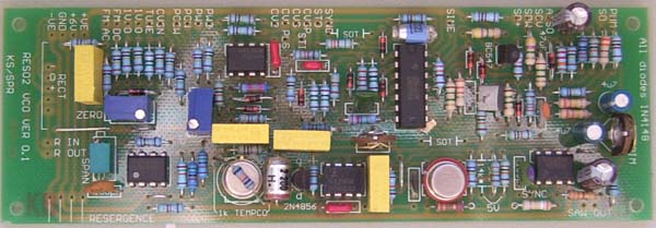
This is one of those PCBs than can be assembled in a number of different ways to suit the builder's panel space or "maximum knobs" requirements. Before you start assembly, check the board for etching faults. Look for any shorts between tracks, or open circuits due to over etching. Take this opportunity to sand the edges of the board if needed, removing any splinters or rough edges. When you are happy with the printed circuit board, construction can proceed as normal, starting with the resistors first, followed by the IC socket if used, then moving onto the taller components. Take particular care with the orientation of the polarized components such as electrolytics, diodes, transistors and ICs. When inserting ICs into sockets, take care not to accidentally bend any of the pins under the chip. Also, make sure the notch on the chip is aligned with the notch marked on the PCB overlay. The tempco resistor needs to be in physical contact with the matched transistor pair (LM394, MAT02 etc). For this reason it has been positioned on the PCB so that it goes diagonally across this chip. Make sure that the wires of the tempco do not touch the body of the transistor pair if it is of the metal can variety. A small amount of thermal compound (heatsink grease) should be put between the body of the tempco and the transistor pair, then the two held together snugly with a common wire tie (not yet fitted in the photo at the top of this page). The "Tune" input on the PCB is set for dual rate operation. The pot must be wired between the +VE and -VE supplies, with the wiper to the tune input. Clockwise from around 12 oclock, the response will be a finer than anti-clockwise from this point, where the 1N4148 diode and extra resistor come in to play. This is to allow the VCO to be easilly cranked down to LFO speeds. The diode can be omitted if you do not want this functionality. A fine-tune control can be added by wiring a second pot as per the tune control, but wiring the wiper to the CSVN via a high value resistor such as 4M7, or even 10M. The best value for the pots is 100k lin, though 50k lin would be usable. PWM Changes you can make to the PWM circuit on earlier versions so you can add an initial setting pot and extra inputs: Increase the value of the existing 1k input resistor to 100k. Mix your second input via another 100k to pin 6. Add extra inputs in the same way. If you need extra range, increase the existing 100k pulldown to 470k. The latest version of the PCB (Ver 1.0) has two 100k resistors in place of the 1k, giving two inputs. The pulldown is still specified as 100k. REV 0.2 corrections. Modifications to the PCB are as follows:
REV 0.4 corrections. Modifications to the REV 0.4 and (probably) earlier PCBs are as follows:
REV 0.5 corrections.
VER 1.0 changes and corrections.
Wiring diagrams for some of the VCO options. Not all options will be relevant, dependant upon the design of the front panel being used. The AC couple outputs are not shown above. The second processor (FREQ CV/LEVEL on diagram) is wired in the same manner as the first, sharing the PCCW and PCW connections.
Setting upThere are several trim pots that need to be adjusted. With no CV inputs connected, and the tune and frequency controls set to their center position, adjust the trim-pot marked "Zero" until there is 0 volts on pin 7 of IC1. The easiest place to connect to this pin is the end of the 100k resistor right next to the text "SP". The next trimmer to adjust is the one marked "Span". Input 1.00 volts into one of the 1V/oct inputs, and adjust the trimmer until the output of the oscillator is exactly one octave higher than when the CV is removed. Now take the input voltage up to 3.00 volts or 4.00 volts, and fine tune this trimmer if needed. The best reference for this process is to have a second VCO or oscillator running at the same time at a fixed frequency. This way, the beat frequency can be used to fine tune. One the volt per octave ratio is correct, the Zero trimmer can be used to set the base frequency of the oscillator (e.g. to tune it to C with no inputs connected). Don't be surprised if this process takes a few times to get right! Once the oscillator is correctly tuned, connect 1.00 volts to one of the prosessor inputs (CV1 or CV2) and adjust the "PRO SP" trimmer until the oscillator runs 1 octave higher with the associated pot fully clockwise. Turning the pot fully anti-clockwise should result in an output frequency one octave lower than with no CV present, and a reversed responce to the CV. "WS TRIM" should be adjusted so that TSO output varies between a sawtooth and a sine wave as the shape control is adjusted. A simpler alternative is to adjust this trimmer until the best sine wave possible is achieved at the "sine" output. Don't expect a perfect waveform - it will most likely have a substancial glitch in it at its best setting. Remember - this sine output is simply there to make use of a spare part of the LM3900 - it is not a key feature of the design. The final adjustment is to "S TRIM". Play with it until the sub-oscillator responds the best over the best possible sweep range. Remember this will not follow the oscillator over its entire range. Again, it is simply there to make use of a spare part of the LM3900 - it is not a key feature of the design.
Notes:
Parts list This is a guide only. Parts needed will vary with individual constructor's needs. If anyone is interested in buying these boards, please check the PCBs for Sale page to see if I have any in stock.
Can't find the parts? See the parts FAQ to see if I've already answered the question. Also see the CGS Synth discussion group.
Article, art & design copyright 2001 by Ken Stone
| |||||||||||||||||||||||||||||||||||||||||||||||||||||||||||||||||||||||||||||||||||||||||||||||||||||||||||||||||||||||||||||||||||||||||||||||||||||||||||||||||||||||||||||||||||