|
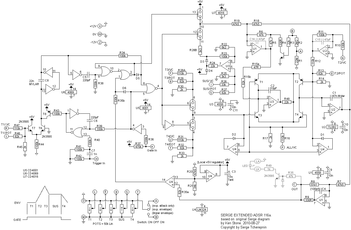
This module is based on the Serge Extended ADSR. In addition to the usual Attack, Decay, Sustain, Release envelope, it has an adjustable delay at the beginning of the envelope. All timings and the Sustain level can be voltage controlled. The envelope can be linear or exponential, or linear with an exponential attack. There is also a master CV input that allows all timings to be reduced at once. When controlled by the same voltage as being used for VCO pitch, this allows for shorter envelopes for higher frequencies, as happens in acoustic instruments. It will work on either +/- 12 volts or +/-15 volts without modification, though in the case of the latter, all input voltage sensitivities, and output voltages are proportionally increased. Note that this design is a little unusual in that the Gate input will sit at "ON" when nothing is connected to its jack. A little on how it works:
Click here to view an enlarged copy of the schematic.
Construction
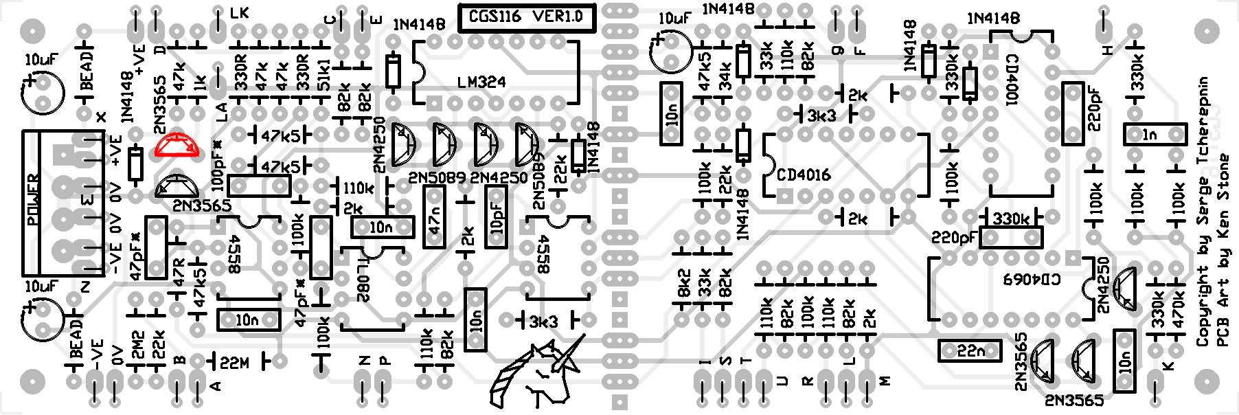
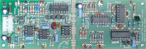
Before you start assembly, check the board for etching faults. Look for any shorts between tracks, or open circuits due to over etching. Take this opportunity to sand the edges of the board if needed, removing any splinters or rough edges. When you are happy with the printed circuit board, construction can proceed as normal, starting with the resistors first, followed by the IC sockets if used, then moving onto the taller components. Take particular care with the orientation of the polarized components, such as electrolytics, diodes, transistors and ICs. Note
When inserting the ICs in their sockets, take care not to accidentally bend any of the pins under the chip. Also, make sure the notch on the chip is aligned with the notch marked on the PCB overlay. Serge's comments re the curious arrangement of R15a 47 ohms in series with R15b 82k: "The curious 47 ohm resistor I remember leaving in the schematic as a means to do in the field adjustments of the total resistance. This had to do with making sure the switching between linear vs exponential decay slopes could be optimized if need be. As it turns out, I never had to do this. So the 47 Ohm resistor can be deleted!" So you can use a 47 ohm, or a piece of wire. The capacitors marked with "*" are additions to the original design to ensure op-amp stability. Transistors and op-amps can be substituted as outlined in the parts list. T1 and T2 should be matched. T3 and T4 should be matched. With modern manufacturing techniqes, transistors from the same batch should be matched well enough that you can skip any hand-matching process. Other than selecting transistors from the same batch, I did no matching. A 1k resistor is specified as the LED resistor. If you use a superbright LED, this value should be increased, to as much as 33k, dependent on the individual LED. Pot values are not critical as they are only used as voltage dividers. Anything between 10k and 100k will work. Pad identification
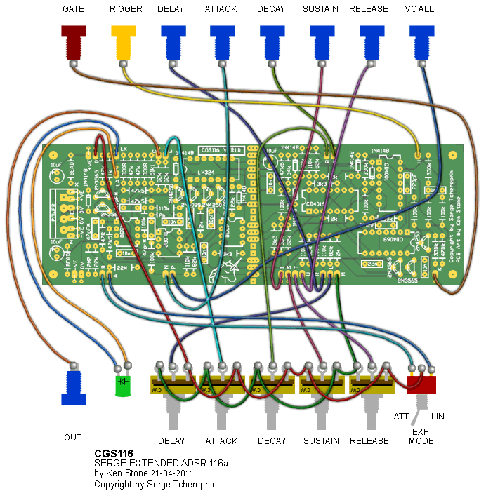
Set UpThere is no setup required. Notes:
Parts list This is a guide only. Parts needed will vary with individual constructor's needs. Alternative part numbers are provided in brackets (). Make sure that you use 4000 series CMOS, and not a 74HCx4xxx variant. If anyone is interested in buying these boards, please check the PCBs for Sale page to see if I have any in stock. Can't find the parts? See the parts FAQ to see if I've already answered the question. Also see the CGS Synth discussion group.
Article, art & design copyright 2010 by Ken Stone
| |||||||||||||||||||||||||||||||||||||||||||||||||||||||||||||||||||||||||||||||||||||||||||||||||||||||||||||||||||||||||||||||||||||||||||||||||||||||||||||||